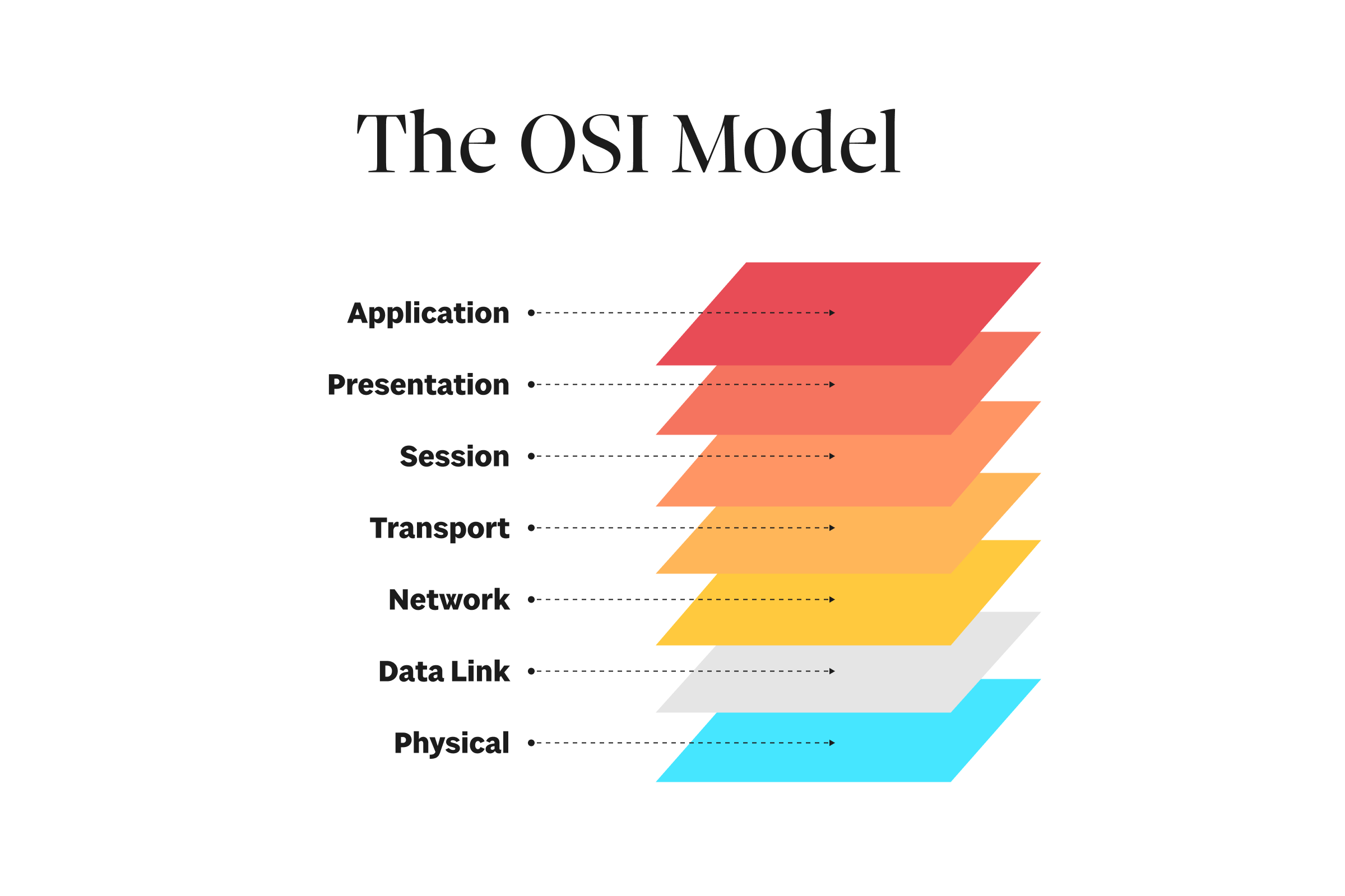
What Is the OSI Model?
The OSI Model is the fundamental framework used in network communication. It is a set of rules that determines how networked devices communicate with and understand one another.
Thanks to the OSI Model, devices at any two points in the world can now communicate with each other. In short: The OSI Model is a set of protocols that defines how networked devices communicate with each other using a common protocol, and it explains how this communication takes place across seven layers.
7. Application Layer
- This is the layer closest to the user.
- Network communication is initiated at this layer using various software applications (Chrome, WhatsApp, Mail, Skype).
- Protocols such as HTTP, SMTP, POP3, IMAP, FTP, and TFTP are used here.
- This is where communication is initiated.
6. Presentation Layer
- Converts data sent by the client into a format that the application on the other device can understand.
- Operations such as encryption, decryption, and compression are performed at this layer.
- File formats such as GIF, JPEG, TIFF, ASCII, and MP4 are handled in this layer.
5. Session Layer
A session must be established for communication between the client and server. The Session Layer facilitates this connection.
- It synchronizes the two devices with each other before data is sent or received.
- It manages the session to ensure it is initiated, terminated, and that the correct data is associated with the correct session.
Example: On websites where you log in by creating an account, a session is initiated the moment you access the site. If there is no activity on the site for a certain period, you will see that you have been logged out of your account—this is a clear example of a session’s use case.
4. Transport Layer
The transport layer is responsible for breaking data into segments and reassembling them. The data generated at this layer is called a segment or a datagram.
| TCP | UDP |
|---|---|
| Slower than UDP | Faster than TCP |
| Aims for secure and complete transmission | Aims for high throughput |
| Establishes a connection (three-way handshake) | Does not establish a connection |
| Sequences data | Does not sequence data |
| Provides acknowledgments | Does not provide acknowledgments |
| Resends corrupted packets | Does not resend packets |
3. Network Layer
If data is to be sent to a different network, the Network Layer handles this task.
- By adding the sender, recipient, and additional information to the segments received from the transport layer, it ensures the data reaches the intended device on the target network.
- During data transmission, it attempts to select the shortest path to the destination.
- IPv4, IPv6, ARP, and ICMP are protocols that operate at this layer.
- The data formed at this layer is called a packet.
- A router operates at this layer.
IP addresses enable access to different networks. When a packet is sent or received, the IP address remains unchanged throughout the transmission path. ARP spoofing is one of the types of attacks that occur at this layer.
2. Data Link Layer
- Controls the transfer of data received from the Network Layer to the physical medium.
- Is responsible for the physical transmission of data between devices.
- It is used for communication within the same network.
This layer is divided into two parts:
- MAC (Media Access Control): Responsible for data encapsulation and media access control.
- LLC (Logical Link Control): Establishes communication between the network software in the upper layer and the device hardware in the lower layer.
Encapsulated data in the Data Link layer is called a frame. A frame consists of header and trailer information. When the destination MAC address reaches the NIC card on the other end, if it does not match its own MAC address, the frame is immediately discarded.
1. Physical Layer
Before any network communication can take place, a physical connection to a local network must be established. Depending on the network configuration, this connection can be wired or wireless.
The Physical Layer transmits the encapsulated data—which takes its final form at the Data Link layer—to the other end in the form of bits (0s and 1s) via wired or wireless means. This layer involves cables (UTP, STP, fiber), connectors (RJ45), NIC cards, and hubs.
Some standards:
- Ethernet (IEEE 802.3)
- Bluetooth (IEEE 802.15)
- WLAN (IEEE 802.11)
Join the conversation
Comments are provided by GitHub Discussions through Giscus.